Raspberry Pi 40 Pin Gpio Easy Connector
The Raspberry header is the key to its ability to interface with the real world. The Pi either uses a 40-pin or 26-pin depending on the model and it is important to understand how those pins are arranged and labelled.
The GPIO header provides the following power and interface options :
- 3.3V (on 2 pins)
- 5V (on 2 pins)
- Ground (on 8 pins)
- General purpose input and output
- PWM (pulse width modulation)
- I2C
- I2S
- SPI
- Serial
These allow a massive range of sensors, motors, LEDs and accessories to be connected to the Pi.
Raspberry Pi 40-pin GPIO Header
The majority of Raspberry Pi models use the same 40-pin header :
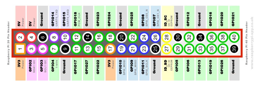
If you are reading the Raspberry Pi copyright statement printed on the PCB then Pin 1 is in the bottom left and Pin 40 is in the top right.
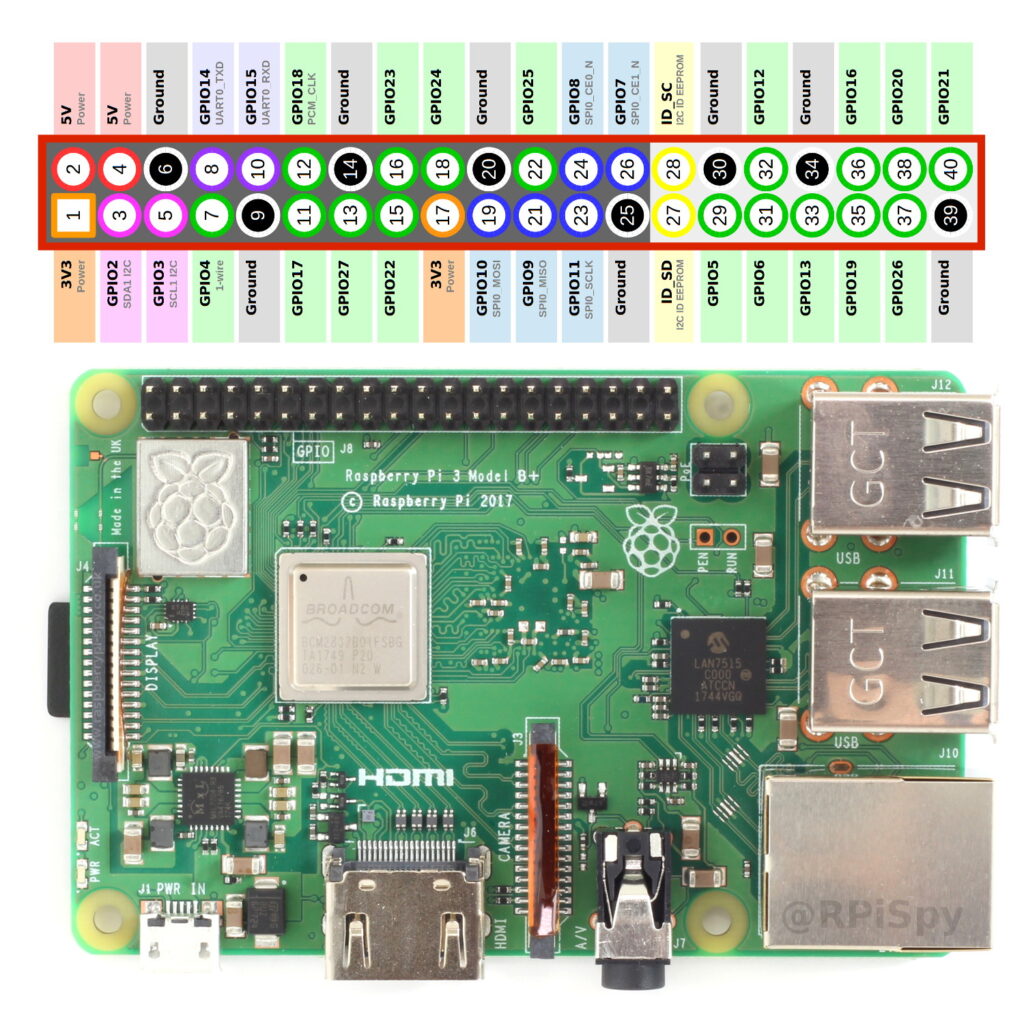
The models that use this configuration are :
- Pi 4 Model B
- Pi 3 Model B+
- Pi 3 Model B
- Pi 3 Model A+
- Pi 2 Model B
- Pi Model B+
- Pi Model A+
- Pi Zero
- Pi Zero W
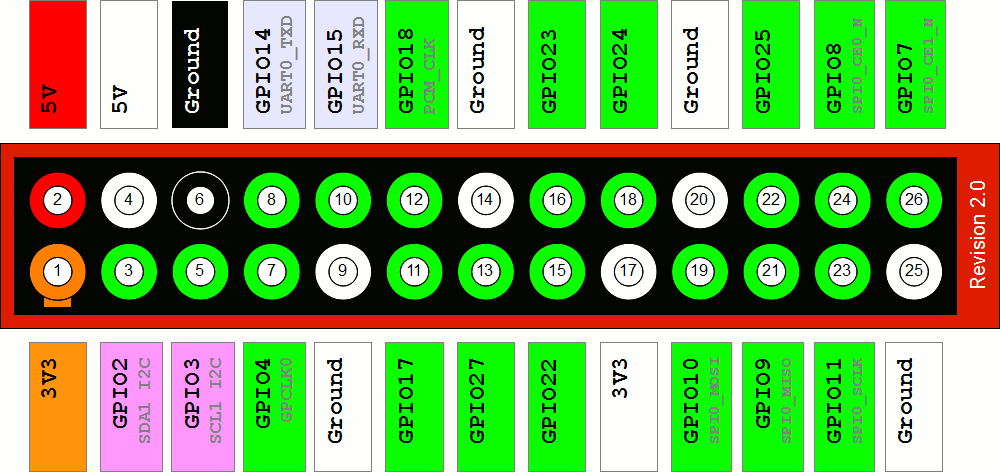
Pi 1 Model A/B (Revision 2.0)
Revision 2.0 saw some slight changes to Pin 3, Pin 5 and Pin 11. These changes carried over to the new 40-pin design so anything that worked on a Revision 2.0 model should work on the newer models.
Pi 1 Model B (Revision 1.0)
This is where it all began. The original 26-pin GPIO header :
It consists of two rows of thirteen pins. Pin 1 is clearly marked on the board as "P1". It is vital you are looking at the header the correct way round. Locate "P1" and compare the header to the diagram below :
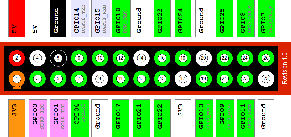
The Pin marked "P1" is Pin 1 and provides 3.3V (50mA max). You can work out all the other pins from there. Note how the numbering works. Even numbers on the top row and odd numbers on the bottom row.
The white pins were previously "DNC" (Do Not Connect) as they were reserved for future use. It was eventually confirmed that their function would not be changed so the diagrams above showed their permanent assignment.
To find out what board revisions you have take a look at my Guide to finding out your PCB revision number.
Pin Labels – Clear as Mud
The labels above are the names of the pins on the Broadcom system chip to which the pin is physically connected. Much of the confusion around the GPIO is due to these labels, their relationship to the Broadcom labels and how they are referred to in your programs. To confuse things even more the GPIO pins are sometimes renamed with another set of numbers. In order to avoid damaging your Pi you need to be sure what pins you are connecting to other hardware and that your program is referring to the correct pins.
GPIO Header Power Pins
The header provides 5V on Pin 2 and 3.3V on Pin 1. The 3.3V supply is limited to 50mA. The 5V supply draws current directly from your microUSB supply so can use whatever is left over after the board has taken its share. A 1A power supply could supply up to 300mA once the board has drawn 700mA. Power management has been improved with each iteration of hardware.
Basic GPIO
The header provides 17 Pins that can be configured as inputs and outputs. By default they are all configured as inputs except GPIO 14 & 15.
In order to use these pins you must tell the system whether they are inputs or outputs. This can be achieved a number of ways and it depends on how you intend to control them.
GPIO in Python
The easiest way to control the GPIO pins is using the RPi.GPIO Python library. Installing the library is easy if you follow my RPi.GPIO Installation Guide. Once installed using the pins is as easy as :
import RPi.GPIO as GPIO # Use GPIO numbers not pin numbers GPIO.setmode(GPIO.BCM) # set up the GPIO channels - one input and one output GPIO.setup(7, GPIO.IN) GPIO.setup(8, GPIO.OUT) # input from GPIO7 input_value = GPIO.input(7) # output to GPIO8 GPIO.output(8, True)
In this example we use GPIO7 (pin 26) and GPIO8 (pin 24). Python scripts that use the GPIO library must be run using sudo. i.e.
sudo python yourscript.py
Pin Protection
Most of the pins in the header go directly to the Broadcom chip. It is important to carefully design the components you attach to them as there is a risk you will permanently damage your Pi. Short circuits and wiring mistakes could also ruin your day so double check everything. A multimeter is probably going to help a lot here as you can double check wiring before you connect to the Pi.
Circuits
Luckily there are some basic circuits that you can use to protect the pins and the cost of implementing them is minimal. Here are some links to circuits I have built :
Controlling an LED using a GPIO pin
Source: https://www.raspberrypi-spy.co.uk/2012/06/simple-guide-to-the-rpi-gpio-header-and-pins/
Post a Comment for "Raspberry Pi 40 Pin Gpio Easy Connector"